No products in the cart.


We, Confianca Pharmazon (Confianca Technologies LLP) have developed lab at Ahmedabad for Library Preparation. 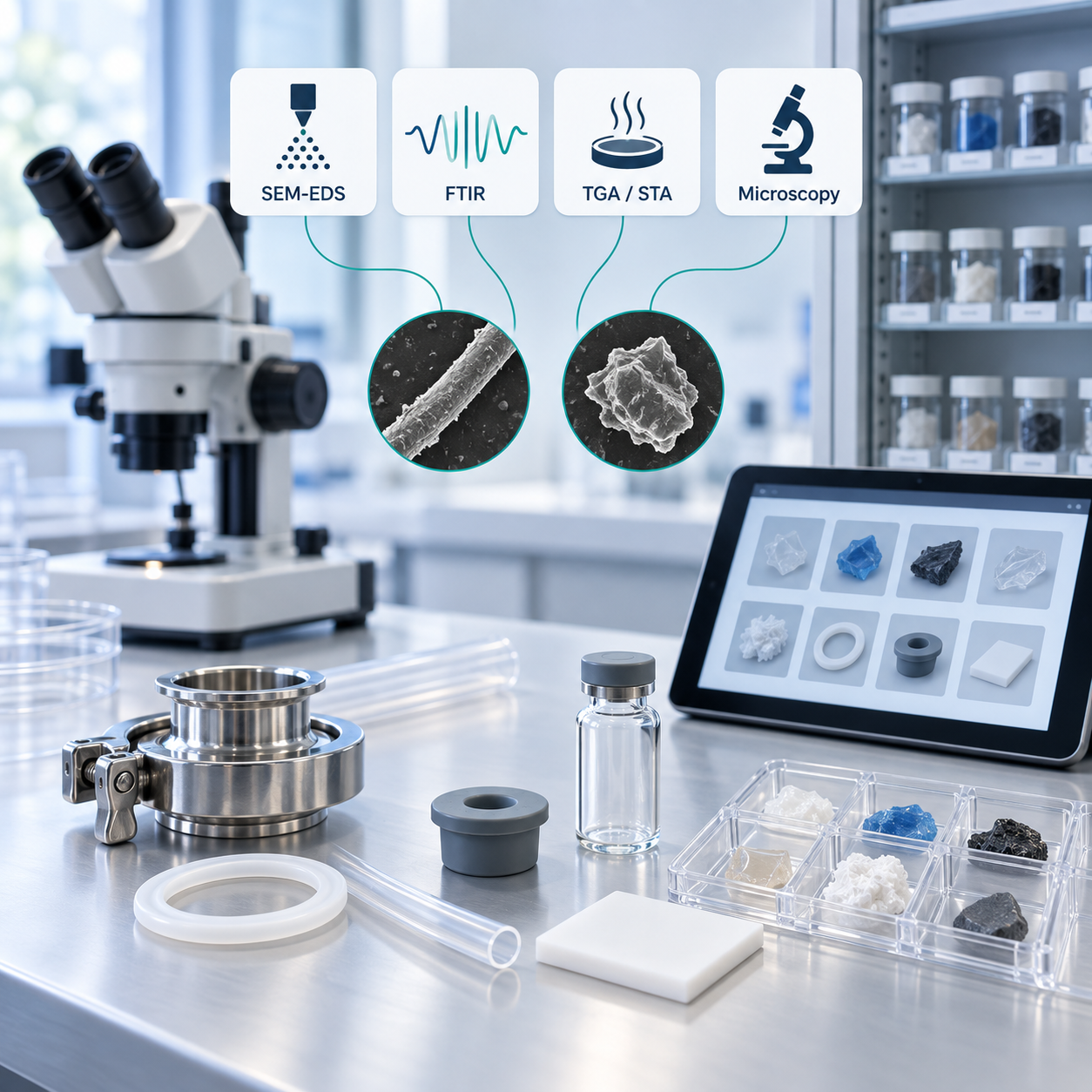
| Library Preparation :- |
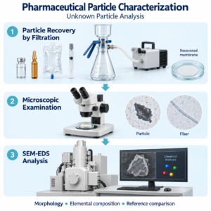
We do Gemba along with client (optional) to identify the product contact and non-contact parts. Based on identification of these parts, coupons shall be collected from clients. Further Analysis of these coupons shall be done at lab using 4 different technologies :- SEM with EDS, FTIR, TGA/STA and Microscopic Analysis. Confianca Pharmazon, a division of Confianca Technologies LLP, provides pharmaceutical particle library preparation services in Ahmedabad, India. We characterise product-contact and non-contact materials to build reference libraries that support particle identification and contamination source investigations. Our service combines SEM-EDS, FTIR spectroscopy, thermal analysis and microscopy, with techniques selected according to the material and project requirements. These reference profiles help pharmaceutical teams compare unknown particles with potential sources within their manufacturing environment. |
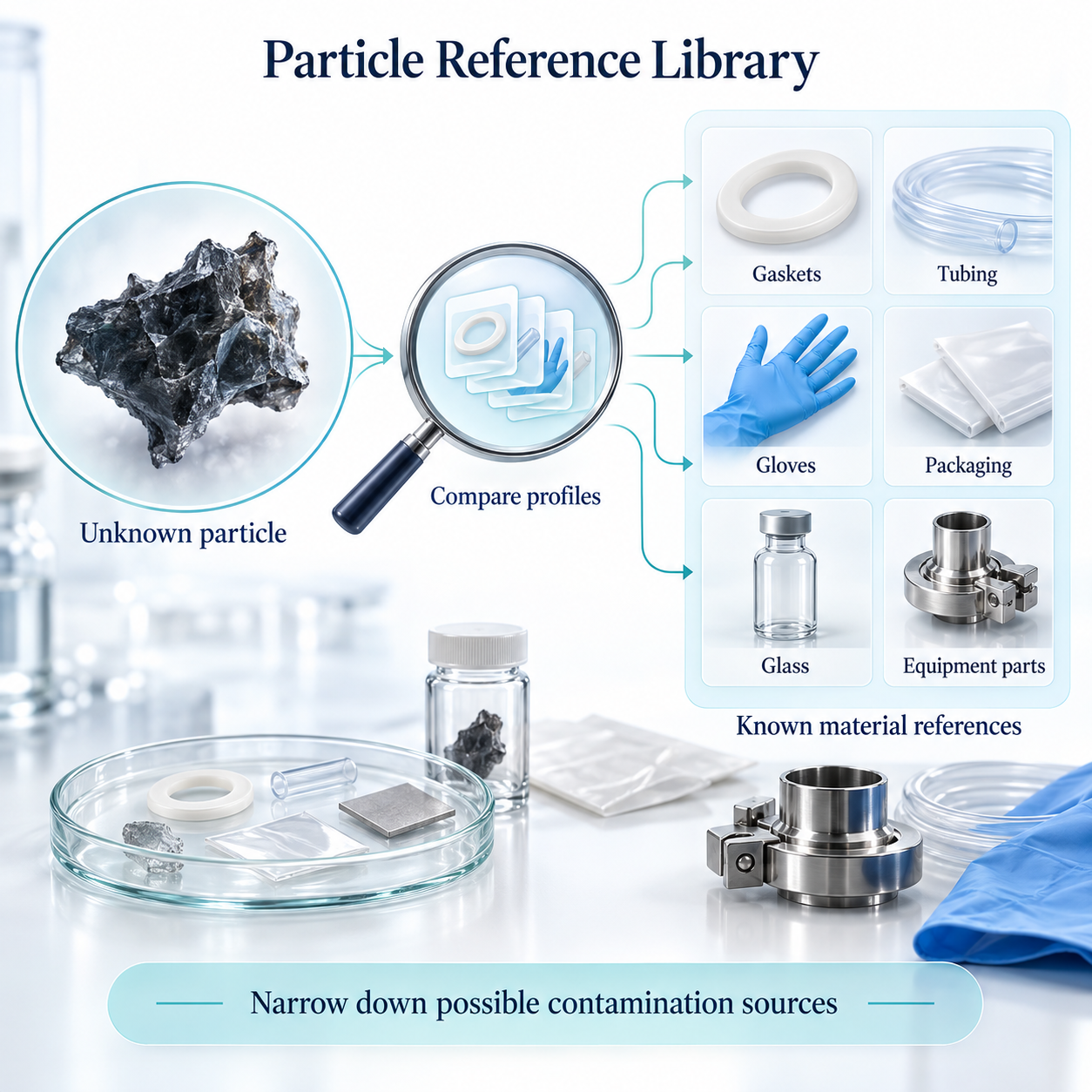
| What Is a Pharmaceutical Particle Reference Library? |
A particle reference library is an organised collection of analytical profiles from known materials used in a pharmaceutical facility. These may include equipment components, gaskets, tubing, gloves, packaging and other materials that could contribute particles to the manufacturing environment. When an unknown particle is detected, its analytical characteristics can be compared with relevant library entries. This comparison helps narrow down possible contamination sources and supports further investigation. |
| Our Library Preparation Process |
| 1. Identify relevant materials We work with your team to identify product-contact and non-contact components for inclusion in the library. An optional Gemba walk supports assessment of materials used across the manufacturing process.2. Collect and document reference samples Representative samples or material coupons are collected from the client and assigned identification codes to connect analytical results with the corresponding component.3. Characterise the materials We analyse the samples using suitable techniques based on the agreed study scope and material characteristics.4. Compile the reference library Analytical results are organised into a material reference library for comparison during future particle investigations. |
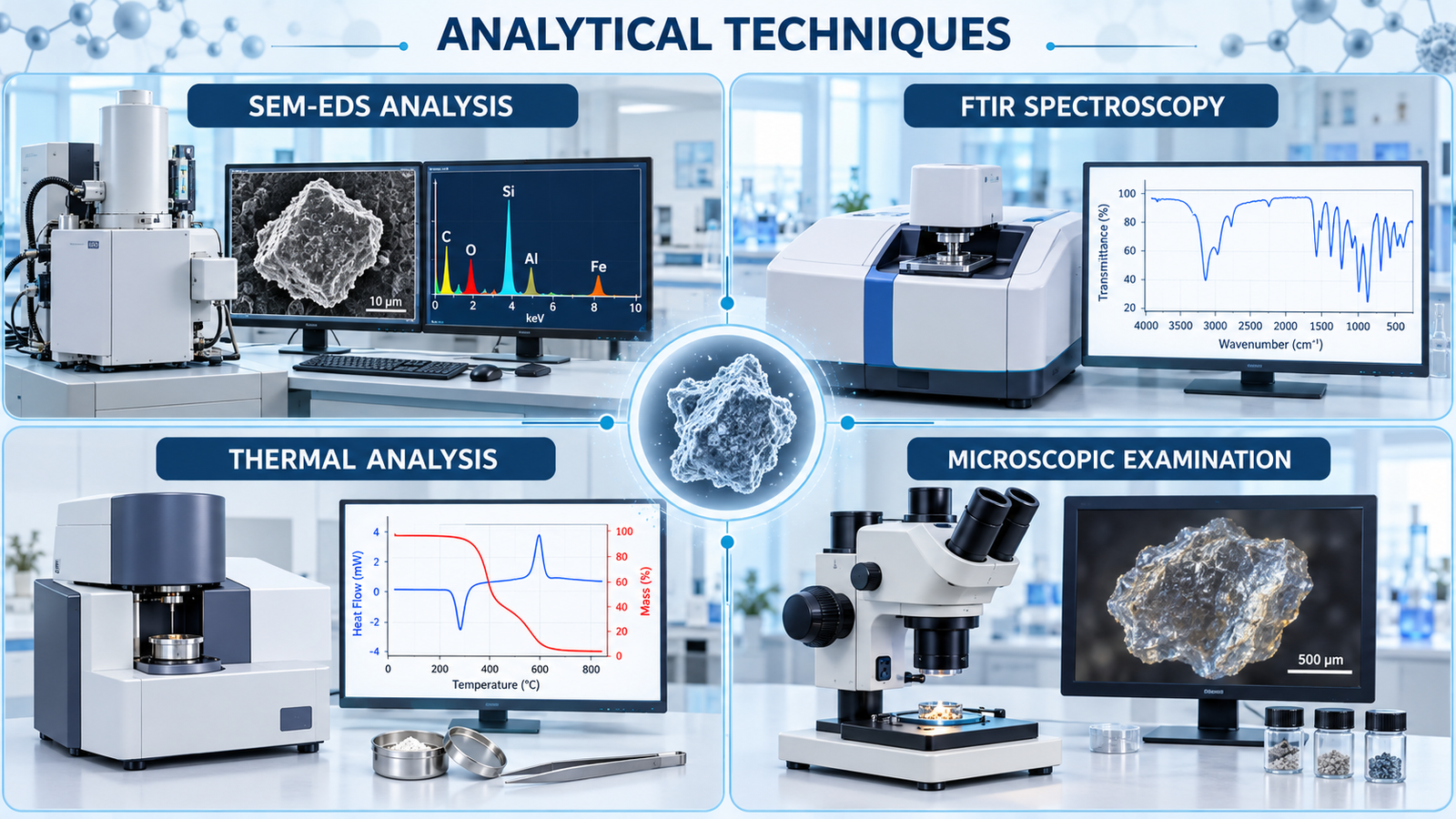
| Analytical Techniques |
SEM-EDS Analysis FTIR Spectroscopy Thermal Analysis Microscopic Examination The combination of techniques depends on the sample and investigation objective. A library comparison supports identification of a probable source; confirmation also requires manufacturing-process evidence. |
| Materials That Can Be Included |
Depending on your facility and study scope, the library may include:
|
| Library Documentation |
Depending on the agreed scope, documentation may include a sample identification register, component descriptions, microscopic images, elemental profiles, FTIR spectra, thermal-analysis results and supporting observations. The objective is to create an accessible reference connecting each tested material with its analytical characteristics. |
| How the Library Supports Your Team |
A facility-specific reference library helps quality, laboratory, production and engineering teams:
|
Sample Library Preparation: We Indetified below Metioned Material for Charaterization
| Sr. No. | Name of Material |
| 1 | PP Container |
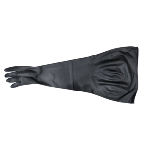
| 2 | Hypalon Gloves for API Addition |
| 3 | TC Clamp of Pressure Vessel |
| 4 | Teflon Bush of Hydraulic cylinder |
| 5 | Product Filter |
| 6 | Gasket (Manual Valve) |
| 7 | Gasket of Pressure Vessel |
| 8 | 2ml Syringe for addition of glacial Acetic acid solution in PP Container |
| 9 | Pharma Pure tubing |
| 10 | Measuring Cylinder (for addition of glacial acetic acid Solution) |
| 11 | Ceramic |
| 12 | Plunger rod with rubber stopper |
| 13 | Poly bag for API |
| 14 | SS Scoop |
| 15 | Glass bottle for Glacial Acetic acid |
| 16 | Hypalon gloves for RM dispensing. |
| 17 | Glass bottle for WFI collection and Glacial acetic acid solution preparation |
| 18 | 2.0 Ltr Pressure vessel (Transfer prepared solution of glacial acetic acid) |
| 19 | Glass bottle for Filtered Glacial acetic acid. |
| 20 | SS scoop for API addition. |
| 21 | SS Spatula |
| 22 | Glass Beaker for Filtered Glacial Acetic acid solution |
| 23 | 2 ml Syringe for sampling |
| 24 | Hydration Hopper |
| 25 | Manual Valve connect to bottom of Hydration hopper to Mixing/Product chamber. |
| 26 | TC clamp (Manual valve) |
| 27 | Mixing/ Product Chamber |
| 28 | Gasket of Hydraulic cylinder (Hydration hopper) |
| 29 | TC clamp Hydraulic cylinder (Hydration hopper) |
| 30 | Teflon bush of Mixing/ Product chamber. |
| 31 | Gasket of Mixing/ Product chamber. |
| 32 | TC clamp Mixing/ Product chamber. |
| 33 | Teflon bush of Hydraulic cylinder of Mixing/ Product chamber. |
| 34 | SS Blind for closer of Mixing/ Product chamber front and back |
| 35 | Viscotec pump (Outer body) |
| 36 | Rotar of Viscotec pump |
Techniques and Instruments used for the Characterization of Library
| TECHNIQUE USED | INSTRUMENT USED |
| Elemental Profiling (By Scanning Electron Microscope with EDS (Energy Dispersive Spectroscopy) | SEM Instrument: Hitachi SU 3800 EDS Detector: Smart EDX |
| Infrared Spectroscopy (By FTIR Spectroscopy) | FTIR-4X |
| Thermal Analysis | The Hitachi NEXTA STA 200 |
| Microscopic Imaging | Magnus TZM6 stereomicroscope (Sr. No. 25G259) |
| LIST OF ANNEXURES |
| (1) Annexure 1 – Elemental Analysis of Target Elements (1.1) Overview (1.2) Standard Operating Procedure for Elemental Analysis using SEM with EDS (1.3) Sample Identification Codes for Elemental Analysis and Elemental Matrix (1.4) Elemental Profiling Table Showing Percentage Composition of Elements Observed in Different Materials |
| (2) Annexure 2 – Material Fingerprint Profiling through IR Spectroscopy (2.1) Overview (2.2) Standard Procedure for IR Analysis using FTIR (2.3) Sample Identification Codes for IR Data (2.4) Characteristic IR Peak Data for Different Positions (2.5) Original IR Data Records |
| 3) Annexure 3 – Thermal Characterization by DSC, Thermogravimetric Analysis (TGA), and Derivative Thermogravimetric Analysis (DTG) (3.1) Introduction (3.2) Standard Operating Procedure (SOP) for Thermal Characterization by DSC, TGA, and DTG (3.3) Observation Results |
| (4) Annexure 4 – Microscopic Examination (4.1) Overview (4.2) Standard Procedure for Microscopic Examination (4.3) Sample Identification Codes for Microscopic Data (4.4) Microscopic Observation Data |
(1.1) INTRODUCTION
Scanning Electron Microscopy with Energy Dispersive Spectroscopy (SEM-EDS) is an advanced analytical technique used for the characterization and elemental identification of particulate matter and contaminants. The technique combines high-resolution imaging capabilities of Scanning Electron Microscopy (SEM) with elemental composition analysis provided by Energy Dispersive Spectroscopy (EDS).
SEM enables detailed examination of particle morphology, including shape, size, texture, and surface characteristics, whereas EDS facilitates identification and semi-quantitative determination of elemental composition through X-ray emission generated from the sample during electron beam interaction.
SEM-EDS is extensively applied in contamination investigations, material characterization, and root cause analysis of particulate matter due to its ability to identify unknown contaminants while preserving the structural integrity of the sample. The technique is particularly useful for differentiating metallic, polymeric, glass, rubber, and extrinsic particulate contaminants encountered during routine manufacturing processes.
(1.2) STANDARD OPERATING PROCEDURE FOR ELEMENTAL ANALYSIS BY SEM WITH EDS
Sample Preparation for SEM-EDS Analysis
STEP 1: Sample Preparation
The particulate sample is visually examined and prepared based on its physical state. Liquid and semi-solid samples, where applicable, are dried under controlled temperature conditions (30–40°C) to remove excess moisture before analysis.
STEP 2: Sample Mounting
The selected particulate matter is carefully mounted onto a standard SEM specimen disc (50 mm or 125 mm) using appropriate adhesive tape:

The sample is positioned carefully to avoid particle displacement during analysis.
STEP 3: Conductive Coating using Gold (If required)
Non-conductive samples are coated with a thin conductive layer of gold to minimize charging effects during electron beam interaction. The thickness of the conductive coating is selected according to sample characteristics to ensure proper imaging and elemental detection.
STEP 4: Vacuum Generation
The mounted sample is placed inside the SEM chamber. The instrument is operated under vacuum conditions, typically requiring approximately 5 minutes to establish the required vacuum environment before analysis.
STEP 5: Electron Beam and Imaging
The electron beam generated through a tungsten filament source is focused onto the sample surface using condenser and objective lenses. Appropriate imaging conditions are selected depending on the sample type:
Working Distance:
Accelerating Voltage:
Multiple microscopic images are captured at suitable magnifications to evaluate particle morphology, surface characteristics, and contamination features.
STEP 6: Elemental Analysis by EDS
The targeted particulate region is subjected to EDS analysis to identify elemental composition. The emitted X-ray spectra are analyzed to determine:
Multiple scans may be performed to improve data reliability and reproducibility.
STEP 7: Data Evaluation
The obtained SEM images and EDS elemental profiles are reviewed and interpreted to support contaminant identification, material differentiation, and contamination source investigation.
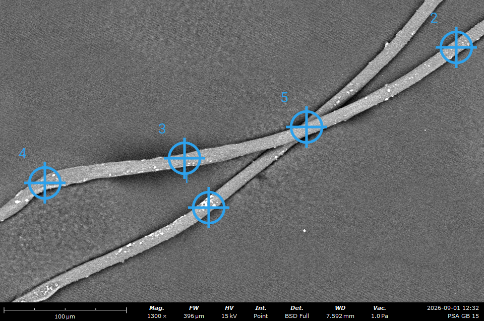
Example of SEM with EDS data of Sample Id. Exp-001.
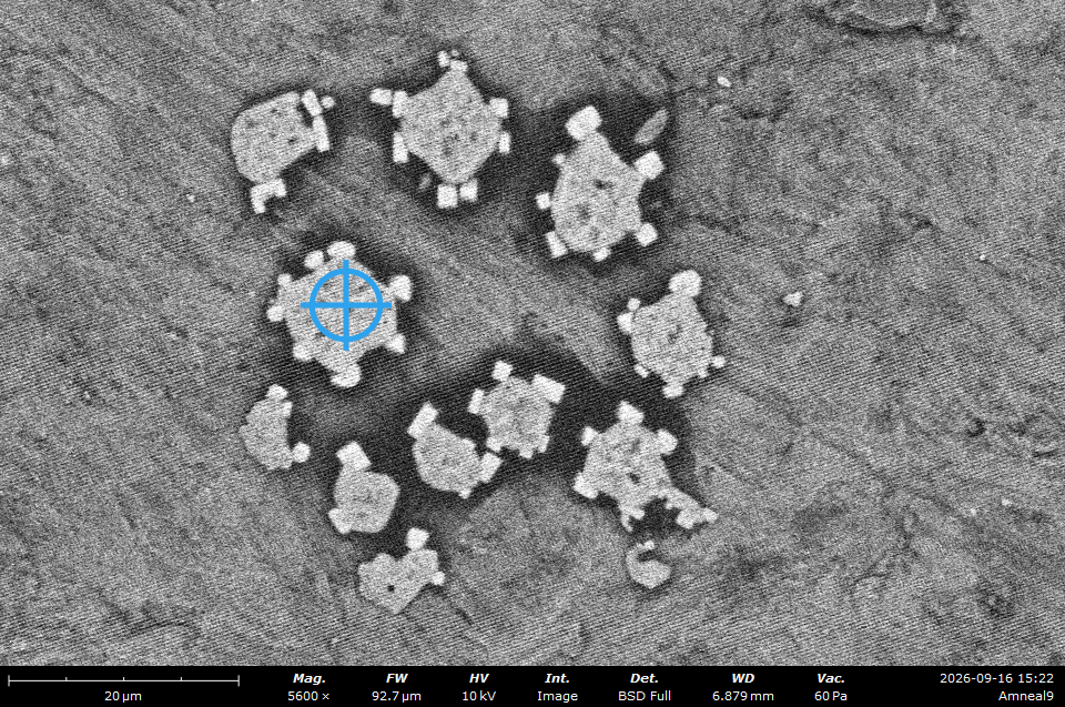
Example of SEM with EDS data of Sample Id. Exp-002.
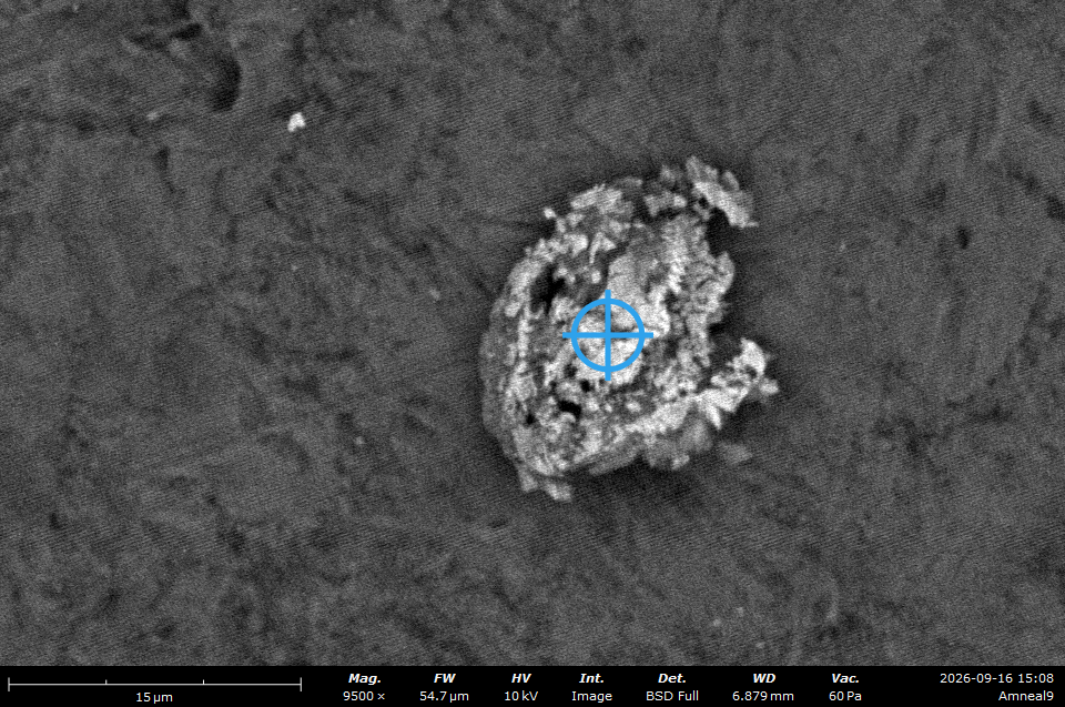
Example of SEM with EDS data of Sample Id. Exp-003.
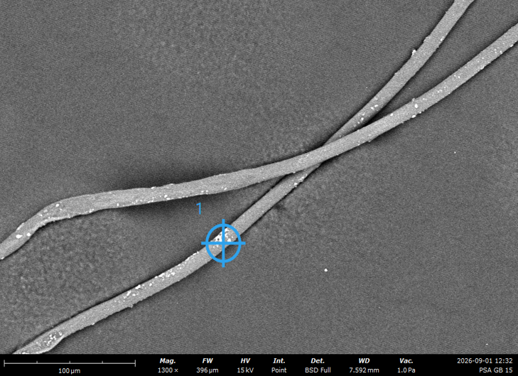
Example of Electron Image of Sample Id . Exp-001: Site 1
Example of EDS Monograph of Sample Id . Exp-001: Site 1
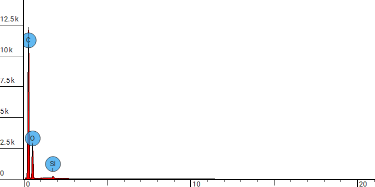
Example of EDS Monograph Table of Sample Id . Exp-001: Site 1
| Element Number | Element Symbol | Element Name | Atomic Conc. [%] | Weight Conc. [%] |
| 6 | C | Carbon | 66.35 | 59.50 |
| 8 | O | Oxygen | 33.31 | 39.80 |
| 14 | Si | Silicon | 0.33 | 0.70 |
2.1 Introduction
Fourier Transform Infrared (FTIR) Spectroscopy is an analytical technique utilized to identify the chemical composition and molecular characteristics of materials through the absorption of infrared radiation. When infrared energy interacts with a sample, molecular vibrations occur within chemical bonds, generating an interferogram. This interferogram is subsequently converted into an infrared (IR) spectrum, which provides valuable information regarding the molecular structure and functional groups present in the material. FTIR analysis is widely employed for material identification, contamination assessment, and comparative fingerprint profiling.
2.2 Standard Operating Procedure (SOP) for FTIR Analysis
Step 1: Instrument Initialization
Step 2: Instrument Preparation
Step 3: Parameter Setting and Background Acquisition
Step 4: Sample Analysis
Step 5: Data Processing and Post-Analysis Cleaning
(2.3) CHARACTERISTIC IR PEAK POSITION FOR VARIOUS SAMPLES
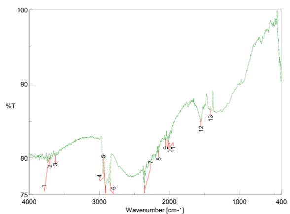
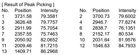
IR DATA: Exp:001
3.1 Introduction
Differential Scanning Calorimetry (DSC), Thermogravimetric Analysis (TGA), and Derivative Thermogravimetric Analysis (DTG) are advanced thermoanalytical techniques used for evaluating the thermal behavior, thermal stability, and physicochemical properties of materials under controlled heating conditions.
Differential Scanning Calorimetry (DSC) measures the heat flow associated with thermal transitions occurring in a material as a function of temperature or time. The technique provides information regarding melting behavior, crystallization, glass transition temperature (Tg), phase transformation, and thermal stability of materials.
Thermogravimetric Analysis (TGA) evaluates changes in sample mass with increasing temperature, thereby enabling assessment of thermal degradation, decomposition profile, volatile matter, moisture content, and compositional stability.
Derivative Thermogravimetric Analysis (DTG) represents the rate of weight loss as a function of temperature and assists in identifying decomposition stages and maximum degradation temperatures of the material.
Simultaneous thermal analysis enables the acquisition of DSC, TGA, and DTG data in a single experimental run, thereby generating a comprehensive thermal fingerprint profile for material characterization, comparative analysis, and source identification.
3.2 Standard Operating Procedure (SOP) for Thermal Characterization by STA
Step 1: Instrument Initialization
Step 2: Sample Preparation
Step 3: Method Setup and Parameter Configuration
Step 4: Thermal Analysis
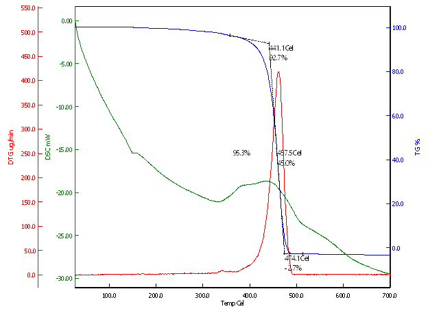
Step 5: Data Analysis and Interpretation
Step 6: Post-Analysis Cleaning and Shutdown
4.1 Introduction
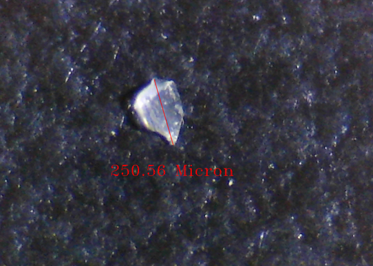
Microscopic analysis is a widely used analytical technique for examining the structural and morphological characteristics of materials, chemicals, and particulate matter at micro and nano scales. The technique enables detailed evaluation of particle size, shape, surface texture, and structural features, thereby assisting in material identification and contaminant investigation. Microscopy is particularly useful for understanding the morphology and physical characteristics of unknown particles and foreign matter.
4.2 Standard Operating Procedure (SOP) for Microscopic Analysis
Step 1: Sample Preparation and Observation
Step 2: Image Acquisition and Morphological Assessment
Exp:001: Microscopic Image
1. What is pharmaceutical particle library preparation?
Pharmaceutical particle library preparation involves collecting and characterising known materials from a manufacturing facility to create an analytical reference database. This library helps compare unknown particles with potential contamination sources during investigations.
2. What are product-contact and non-contact parts?
Product-contact parts directly touch the pharmaceutical product during processing, transfer or storage. Examples include tubing, filters, gaskets and filling components.
Non-contact parts do not directly touch the product but may contribute particles to the surrounding environment. Their inclusion depends on their location and potential contamination risk.
3. How does a particle reference library help investigate contamination?
When an unknown particle is detected, its characteristics can be compared with reference materials in the library. Similarities in appearance, elemental composition, molecular fingerprints and thermal behaviour help narrow down potential sources and guide further investigation.
4. Which analytical techniques does Confianca Pharmazon use?
We provide material characterisation using scanning electron microscopy with energy-dispersive X-ray spectroscopy (SEM-EDS), Fourier-transform infrared spectroscopy (FTIR), thermal analysis such as DSC and TGA, and microscopic examination. The combination of techniques depends on the material and agreed study scope.
5. What materials can be included in the reference library?
The library can include gaskets, seals, rubber stoppers, tubing, filters, glass, stainless-steel components, gloves, packaging materials and other relevant manufacturing components. We work with your team to identify materials appropriate to your facility and process.
6. Does every sample require all four analytical techniques?
No. The appropriate techniques depend on the sample’s composition, size, condition and the information required. Complementary methods are selected where they add useful evidence for material identification and comparison.
7. Does Confianca Pharmazon assist with identifying components for library preparation?
Yes. We work with your team to identify relevant product-contact and non-contact materials. An optional Gemba walk can support the assessment of potential particle sources within your manufacturing process.
8. What samples should we provide for library preparation?
Clients generally provide representative material samples or coupons from the selected components. Where available, include the component name, material of construction, supplier details and equipment or process location. Sample quantity and preparation requirements should be agreed before dispatch.
9. What documentation is provided with the library?
Depending on the agreed scope, documentation may include sample identification details, microscopic images, SEM-EDS elemental profiles, FTIR spectra, thermal-analysis results and supporting observations. These records connect each reference material with its analytical characteristics.
10. Can a library match confirm the exact source of an unknown particle?
A match can indicate a probable source, but it does not automatically confirm the exact component responsible. Different components may contain similar materials. Analytical findings should therefore be assessed alongside equipment condition, maintenance history and manufacturing-process evidence.
11. When should a pharmaceutical particle library be updated?
The library should be reviewed when relevant materials, suppliers, equipment or processes change, or when an investigation identifies a potential source that is not already included. Updates help keep the reference information representative of the facility.
12. How can we request a quotation for library preparation?
Contact Confianca Pharmazon with your component list, approximate sample count and analytical requirements. Our team will discuss the scope and provide a quotation.
Phone: +91 9173319482
Email: gaurav@confiancapharmazon.com
Location: Ahmedabad, Gujarat, India




Reviews
There are no reviews yet.